

Water Supply Storage Tanks :-
Water Supply Storage Tanks inside the building can be broadly Classified into:-
- Underground Storage Tanks
- Over Head Storage Tanks
Water Tank Sizing = Number of persons * Per Capita Water Demand
Where there is availability issues, always try to store in U.G Tank and then pump this water to Over Head Tank (O.H.T)
- UG Tank capacity can be 1.5 to 2 days of storage for the building
- Generally, Length of Tank = 2* Breadth
ie; L = 2B
The Drain line from UGWT (Under Ground Water Tank) is generally connected to a drain pump to evacuate the tank while cleaning.
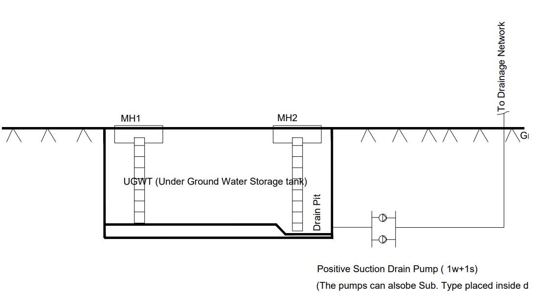
Fig : Under Ground Storage Tank Drain Pump Schematic
The cold water can be supplied by transferring the UG water to an overhead tank, and can be pumped to the floor via. a booster pumping system and also fed by gravity to the lower floors.
The water from OHT is (Over Head Tank) distributed by means of a booster pumping system and gravity head as shown below.
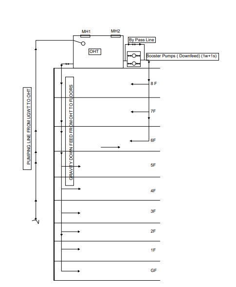
Fig : OHT Down feed Schematic representation ( Gravity and Booster Pump combined system)
The combined gravity feed and Booster pumping system from Over Head Tanks (OHT) has some drawbacks.The pressure may vary at different floor levels and at different outlets, even if the adjustments with pressure reducing valves are made, we cannot fully avoid this draw back.
Hydro Pneumatic System
To avoid the above mentioned drawback, modern water distribution systems in buildings uses Hydro pneumatic systems (up feed from underground storage).
Hydro Pneumatic system ensures equal flow rate and pressure distribution at entire supply outlets at different floors (avoiding two different feed systems ie, Gravity and Booster feed system as mentioned above.
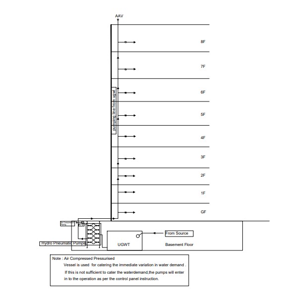
An Air Compressed Water Vessel ( We shall call it Pressure Vessel ) is connected to the delivery side.
A compressor circuit for maintaining the air pressure is connected to the Vessel
Fig : Hydro pneumatic Pumping Schematic representation
Hydro pneumatic system is most ideal for high-rise apartments and commercial buildings with varying demand.
Hydro pneumatic system comprises of 2 to 6 high pressure multistage centrifugal pump sets, valves, base frame, suitable control panel, section and delivery manifolds etc.
The system is pre assembled, tested in factory and ready for installation at site.
The Control panel, controls the number of pump sets to operate based on system discharge and pressure requirements. Pressure vessels( Pls refer noe below digm) are connected to the delivery manifold as shown in schematic diagram; so as to reduce the stops and starts of the pump sets. The system consists of high quality pressure switches, pressure transmitter, pressure vessels, and other accessories.There can be variable or constant speed controller for hydro pneumatic system.The variable speed controller is suitable for smooth operation of supply systems and is highly preferred in almost modern residential and commercial buildings . Immediate small demands in the system is managed by the vessel,if the vessel can not mange the requirements, the control panel activates the pumps accordingly.The control panel controls the number of pumps in operation as per the system discharge and pressure requirements.
(Created on 28-1-24 )
————————————————————